Technical Wiki · No. 10
Power Transformer Accessories, Voltage Regulation and Mechanical Protection: Engineering Overview
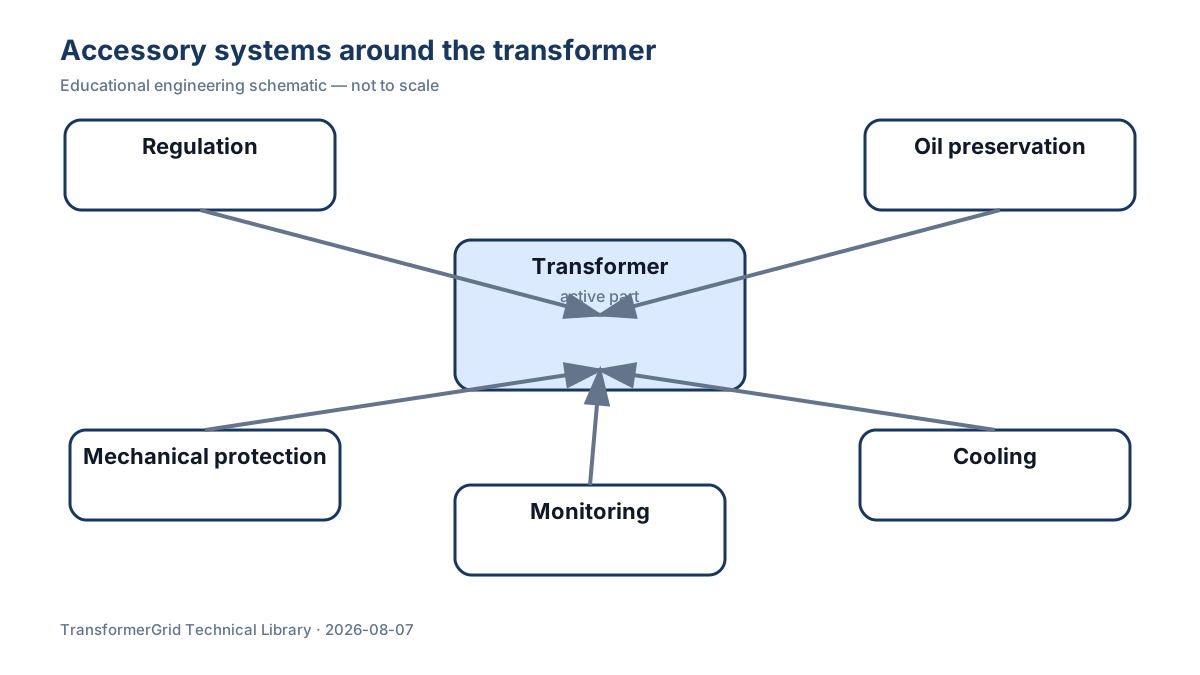
Five interconnected subsystems
The first group is voltage regulation, including de-energized tap changers and on-load tap changers. The second is oil preservation and breathing, including the conservator, bladder or diaphragm, breather and connecting pipework. The third is mechanical protection, including the Buchholz relay, pressure-relief device or safety duct. The fourth is cooling, including radiators, fans, oil pumps, oil-flow relays and auxiliary power. The fifth is monitoring and control, including oil temperature, winding temperature, oil level, local indication, remote signals and cooling-start circuits. These systems are not independent. An abnormal oil level can be related to temperature, leakage, a blocked breather or a bladder problem; a Buchholz operation may need to be evaluated together with DGA, oil level, cooling status and electrical test evidence.
Engineering boundaries of the voltage-regulation system
A de-energized tap changer can change position only after the transformer is isolated and de-energized. An on-load tap changer can change taps while the transformer is energized or carrying load. The procurement difference is not only cost: the operating mechanism, position indication, control supply, remote interface, oil-compartment service and maintenance method are also different. Writing only “tap changer included” in an accessory schedule is not enough. The regulation method, tap range, positions, position indication, local and remote control, interlocks and delivery documents should be defined.
Oil preservation and mechanical protection
The conservator accommodates the expansion and contraction of oil as temperature changes, helps keep the main tank filled and reduces direct contact between the oil surface and ambient air. The breather and sealing system reduce the entry of moisture, oxygen and contamination. The Buchholz relay is installed in the oil path between the main tank and the conservator to detect gas accumulation or abnormal oil movement. A pressure-relief device provides a controlled release path when internal pressure rises abnormally. These devices respond to different physical phenomena and should not be treated in the same way after an operation.
Cooling and monitoring are not secondary functions
ONAN, ONAF, OFAF and ODAF describe different combinations of oil circulation and external cooling. The more the system depends on fans and oil pumps, the more important auxiliary power, staged operation, oil-flow feedback, failure alarms and standby capacity become. Temperature instruments are also more than displays. Local indication, control-panel values and supervisory-system values should form a consistent measurement chain, while alarm contacts, cooling-start contacts and other project outputs should be checked point by point during FAT and site commissioning.
Documents needed for procurement and acceptance
A complete accessory engineering package should at least include the accessory schedule, make/model and quantity, installation-location drawings, oil or pipework diagrams, terminal and signal schedules, local/remote control logic, alarm and trip matrix, calibration or test requirements, spare parts, manuals and final as-built revision records. TransformerGrid does not replace the owner or protection engineer in choosing setpoints. Its role is to organize these cross-discipline interfaces into comparable RFQs, drawing-review sheets, deviation lists and FAT checklists so the manufacturer, designer, owner and site team work from the same approved version.
Conclusion
For a large oil-immersed power transformer, the accessory system should be reviewed along five lines at the same time: function, signal, control, test and documentation. Specific setpoints, alarm logic and trip schemes must follow the project specification, manufacturer documents and applicable operating procedures.
Frequently Asked Questions
Are all transformer accessories standard equipment?
No. Accessory type, signals, controls and tests depend on the transformer design and project specification, so they must be confirmed in an accessory schedule.
Why does this Wiki not give one universal alarm setpoint?
Setpoints and logic depend on manufacturer design, project requirements and operating practices. A single universal number could be misleading.
Technical References
- Qin Ganghua, Wang Zhanhong, Wang Xin, et al. 《火力发电企业绝缘技术监督手册》 [Insulation Technical Supervision Manual for Thermal Power Enterprises]. Zhejiang University Press. Consulted for: Transformer components, tap changers, conservators, Buchholz relays, pressure relief, cooling, core grounding, temperature monitoring and inspection.
- Sun Kejun, et al. 《电工手册》 [Electrical Engineering Handbook]. China Machine Press. Consulted for: Oil-immersed transformer construction, pre-energization checks, tap changers, gas relays, breathers, cooling systems and routine inspection.
- Xu Linbo, Yang Min, Huang Xudong, et al. 《火力发电企业继电保护技术监督手册》 [Relay Protection Technical Supervision Manual for Thermal Power Enterprises]. Zhejiang University Press. Consulted for: Buchholz relay, protection circuits and pressure-relief device inspection boundaries.
- Zhou Qiukuan, Liu Mingjun, Liu Yan, et al. 《电力设备带电检测技术及应用》 [Live Detection Technologies and Applications for Power Equipment]. Jinan University Press. Consulted for: Infrared thermography, dissolved-gas analysis, partial-discharge detection and core-ground lead diagnostics.
Final engineering values, setpoints and operating decisions require written confirmation from the project engineer, owner or utility and manufacturer.