Technical Wiki · No. 16
Transformer Core Single-Point Grounding and Multiple-Ground Faults: Current, Local Overheating and Detection
Why single-point grounding is used
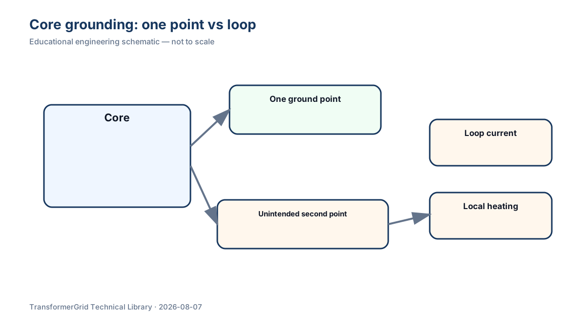
The core and metallic clamping structures operate in an alternating electromagnetic field. A controlled ground limits floating potential. Multiple grounds can close a metallic path that was not intended to carry circulating current. The condition may not immediately operate the main protection, yet it can cause long-term heating, insulation damage or abnormal gas generation.
What should be monitored
Useful evidence includes core-ground insulation resistance, operating ground current, historical trend, dissolved gases, infrared temperature and other live-detection results. A single current reading cannot replace trend analysis, and an unusual value should first be checked for measurement setup, external interference and sensor errors.
Possible sources of multiple grounding
Metal contact left after maintenance, damaged insulation parts, contact involving clamps or shields, metallic particles in oil, lead problems or grounding-device defects can create an unintended second grounding point. Locating the actual path usually requires correlation of outage tests with structural inspection.
Value of live detection
Live-detection cases show that a high-frequency current sensor can be placed on the core-ground lead and its signals compared with UHF detection. These cases also show an important boundary: detecting pulses does not automatically prove internal partial discharge. Multiple methods are needed to determine whether a signal comes from inside the transformer or from external interference.
Principle after an abnormal indication
A sound diagnostic sequence is: confirm the measurement, establish the trend, correlate oil-gas and temperature evidence, locate the unintended path during an outage, remove the non-design ground and repeat the measurements. Whether any temporary current-limiting measure is acceptable, and its parameters, must be decided by the manufacturer and responsible operating engineer for the specific transformer.
Procurement and delivery records
New-equipment documents should define how the core and clamps are grounded, the test terminals, insulation requirements, site measurement conditions and factory baseline values. Preserving baseline data before energization makes future trend interpretation much stronger.
Conclusion
Core-ground current is rarely a simple “above this number is bad, below it is good” value. Its direction, rate of change and correlation with temperature and gas evidence can be more diagnostically useful than one isolated reading.
Frequently Asked Questions
Why should the transformer core not have multiple grounds?
Multiple grounds can create a closed conductive loop, causing circulating current and local overheating.
Is one normal core-ground current measurement enough?
No. Historical trend and supporting diagnostic evidence should also be considered.
Technical References
- Qin Ganghua, Wang Zhanhong, Wang Xin, et al. 《火力发电企业绝缘技术监督手册》 [Insulation Technical Supervision Manual for Thermal Power Enterprises]. Zhejiang University Press. Consulted for: Core single-point grounding, ground insulation, ground-current measurement and abnormal-condition boundaries.
- Zhou Qiukuan, Liu Mingjun, Liu Yan, et al. 《电力设备带电检测技术及应用》 [Live Detection Technologies and Applications for Power Equipment]. Jinan University Press. Consulted for: High-frequency current detection on the core-ground lead, UHF correlation and interference identification.
Final engineering values, setpoints and operating decisions require written confirmation from the project engineer, owner or utility and manufacturer.