Transformer Sound and Vibration: Engineering Fundamentals, Measurement and Diagnosis
Published July 22, 2026 · Engineering coordination review by TransformerGrid · Project-specific requirements require manufacturer, utility and applicable-standard verification.
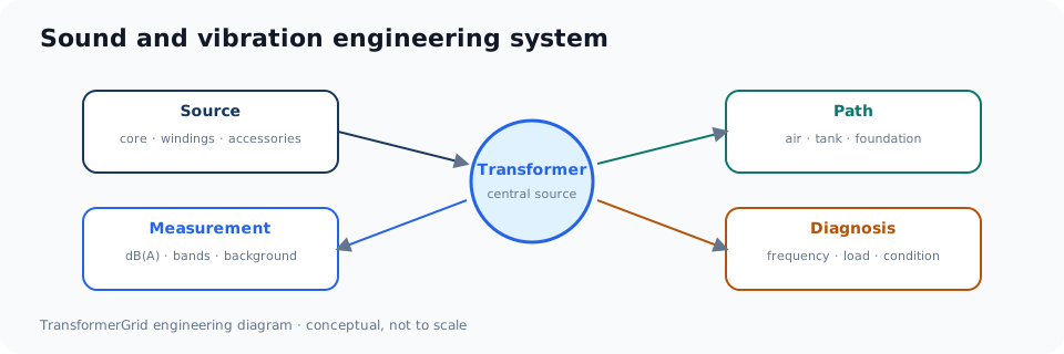
Audible sound during transformer operation does not by itself indicate a defect. A stable low-frequency hum is normally associated with core magnetostriction and electromagnetic forces. Load, waveform distortion, cooling equipment, structural parts and installation conditions alter the spectrum and propagation. Engineering assessment begins by separating the source, path, acoustic quantity and operating state.
Three principal source groups
Core-related sound
Electrical steel changes dimensions slightly under alternating magnetization. Because the strain pattern repeats in both polarities, an important mechanical component commonly appears near twice the power frequency—about 100 Hz in a 50 Hz system and 120 Hz in a 60 Hz system—together with higher components. Material, joints, flux density, residual stress and clamping affect the result.
Load-related sound
Winding current and leakage flux create electromagnetic forces in windings, leads and structural components. The contribution may change with current, harmonics and mechanical condition. A change with load is evidence to investigate, not proof of one particular internal defect.
Cooling and accessory sound
Fans, pumps, bearings and airflow can produce broadband or discrete components. Loose doors, panels, cable supports or external hardware may rattle or resonate.
Sound pressure, sound power and spectrum
Sound pressure level describes pressure at a measurement point:
Lp = 20 log10(p/p0), where p0 = 20 μPa
Sound power level describes total radiated acoustic power:
LW = 10 log10(W/W0), where W0 = 10−12 W
Sound pressure changes with position, distance, reflection and background. Sound power is determined from prescribed sound-pressure or sound-intensity measurements and corrections. Both are expressed in dB but represent different physical quantities.
A-weighted totals support an overall human-response assessment, while octave or narrow-band spectra preserve information about low-frequency tones, harmonics, broadband cooling sources and structural resonances. A spectrum assists diagnosis; it does not prove a fault by itself.
Factory and field assessment
IEC 60076-10 addresses determination of transformer and cooling-equipment sound levels, principally under factory measurement conditions. A field boundary or indoor assessment must also account for local regulations, receivers, buildings, ground, weather and background. Factory compliance and field compliance are related but are not the same acceptance question.
A defensible diagnostic sequence
- Record when and where the sound occurs and whether it is stable, tonal, intermittent, rattling or impulsive.
- Record voltage, frequency, tap, current, load balance, harmonics, temperature and cooling status at the same time.
- Compare with a historical baseline under similar conditions.
- Inspect accessible external components, foundation and connected structures under the applicable safety procedure.
- Escalate to vibration, thermal, oil/DGA, partial-discharge or electrical testing when other evidence justifies it.
Sudden arcing-like, explosive or heavy-impact sounds accompanied by smoke, odor, oil release, rapid temperature rise, bushing abnormality or protection operation require the owner’s emergency and isolation procedure—not close-range recording.
Measurement and diagnosis matrix
| Question | Evidence to record | Common interpretation error |
|---|---|---|
| What is the source? | Core, winding/load forces, cooling equipment, panel or accessory; frequency content and location | Calling every audible tone “core noise” |
| What is the path? | Airborne route, tank radiation, foundation, conduit, wall or connected structure | Changing the transformer before checking a structural transmission path |
| What quantity is reported? | Sound pressure or sound power; weighting, bandwidth, reference quantity and averaging | Comparing two decibel values that represent different quantities |
| What operating state applies? | Voltage, frequency, tap, load, balance, harmonics, temperature and cooling status | Comparing factory no-load data with an undocumented loaded site condition |
| What changed? | Repeatable baseline, time trend, maintenance event, alarm, oil/temperature data and protection records | Diagnosing an internal defect from one recording without corroborating evidence |
Two calculations that prevent common mistakes
Independent sound levels are added logarithmically, not arithmetically:
Ltotal = 10 log10(10L1/10 + 10L2/10 + …)
- Two equal 55 dB sources combine to approximately 58 dB—not 110 dB.
- A 60 dB source combined with a 50 dB source is approximately 60.4 dB; the stronger source dominates.
Background correction is also logarithmic and must follow the governing measurement method. Do not subtract the background value arithmetically from the source-on reading, and do not report a corrected value when the required separation or stability is absent.
What a phone application can and cannot establish
| Useful screening role | Not established without suitable instrumentation and method |
|---|---|
| Record time, location and a repeatable change relative to the same device and position | Contract acceptance or compliance with a specified sound-power method |
| Identify whether a tone, rattle or cooling event is intermittent | Calibrated absolute level, octave-band accuracy or background correction |
| Support a request for a qualified survey with operating data | Internal-fault diagnosis or responsibility for a property-boundary exceedance |
A screening record becomes more useful when it includes distance, orientation, weather, voltage, frequency, load and cooling status. It should trigger a comparable measurement plan—not replace one.
Focused pages in this cluster
- Why transformers hum
- Sound pressure, sound power and decibels
- Measurement conditions and reporting
- Harmonics, V/Hz and load effects
- Normal hum vs abnormal sound
Technical Questions and Engineering Discussion
To discuss transformer specifications, testing, protection or application conditions related to this reference, contact [email protected]. Technical exchanges are welcome.
Primary engineering references
- IEC 60076-10:2016 — determination of transformer and reactor sound levels.
- IEC 60076-10-1:2016 and Amendment 1:2020 — application guidance.
- IEEE C57.136-2023 — sound and vibration guidance for liquid-immersed power transformers.
- NEMA TP 80050-2013 (R2024) — audible sound levels for distribution transformers.
Standards must be applied within their stated scope and the edition incorporated into the project documents. This page is an engineering reference, not a substitute for the governing contract, utility specification or safety procedure.