Neutral, Grounding & Zero-Sequence Compatibility in Parallel Transformer Systems
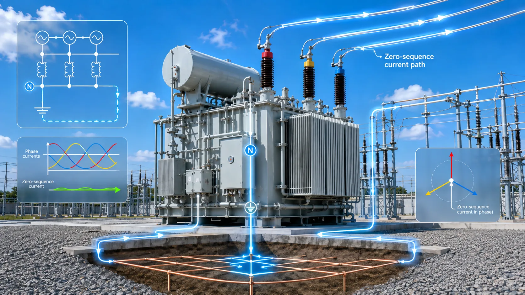
The zero-sequence network is the hidden parallel network
Normal three-phase power is usually considered through the positive-sequence network. Ground faults and neutral current often require a zero-sequence view. Three zero-sequence phase currents are in phase and must have a return path.
For a transformer, whether zero-sequence current can enter or leave a winding depends strongly on winding connection and neutral grounding.
Why the path can change after paralleling
With one transformer in service there is one source/neutral arrangement. Paralleling can add a second neutral point, another grounding path or a common neutral bus. Ground-fault and unbalance current can therefore divide differently than it did in isolated operation.
This may change neutral-conductor current, grounding-conductor current, residual/zero-sequence quantities seen by protection and current balance across CT zones.
Do not replace project grounding design with a universal rule
Systems may be solidly grounded, resistance/reactance grounded, ungrounded or use another project-specific method. Requirements vary by voltage level, country and utility.
The engineering task is to identify where the neutral is, where bonding/grounding occurs, who provides any grounding impedance, how zero-sequence current returns and which conductors are enclosed by protection CTs.
Information and field verification
The design package should show transformer winding connections, neutral terminals, system grounding method, NGR/NER if applicable, neutral-bus/conductor arrangement, main grounding point, ground-fault protection and CT locations.
At site, compare the actual neutral/ground conductors with the approved one-line, remove or control temporary grounds according to procedure, verify CT orientation/conductor inclusion and record neutral current after first paralleling.
Procurement / engineering execution checklist
| Role | Core information / action |
|---|---|
| Buyer / Designer | One-line, winding connections, neutral points, grounding method, NGR/NER, common neutral, CT locations and ground-fault protection. |
| Supplier | Neutral terminal configuration/rating, terminal drawings, grounding equipment within supply scope and CT/interface data. |
| Site / Commissioning | Verify actual neutral/ground conductors and CT paths; record baseline neutral/ground-fault quantities. |
Both Transformers Ran Fine Alone. Why Did Neutral Current Change in Parallel?
Frequently Asked Questions
Does Dyn11 automatically prove grounding compatibility?
No. Dyn11 describes connection and phase displacement; the external zero-sequence path still depends on neutral grounding, external conductors and protection layout.
Does higher neutral current after paralleling prove a transformer fault?
No. Load unbalance, changed zero-sequence paths, grounding connections or measurement/protection layout may also be responsible.
Can the transformer manufacturer alone choose the project grounding method?
Usually no. The manufacturer provides equipment interface facts; the project designer/owner approves system grounding and protection zones.
- Power Transformers and Protection Q&A — operation, paralleling, ratio, vector group, impedance and inrush chapters
- Electrical Engineer’s Handbook, 4th ed. — system connection, transformer impedance and substation engineering
- Relay Protection Technical Supervision Manual — transformer inrush, differential protection and commissioning checks
- Fundamentals of Power Systems — neutral grounding and transformer zero-sequence networks
This article is an engineering and procurement guide. Final paralleling, protection, grounding and switching decisions must follow the project one-line, applicable standards, utility requirements and authorized engineering/commissioning procedures.