Pad Mounted Transformer BIL and Impedance: How to Confirm Insulation Level and Fault Current Before RFQ
Direct Answer: BIL and Impedance Before RFQ
BIL confirms the transformer insulation level for lightning and switching surges. Impedance affects secondary fault current, voltage regulation and protection coordination. A pad mounted transformer RFQ should not rely only on kVA and voltage; it should also state BIL and the required or acceptable impedance range.

Satellite Article #3 update · Lightning impulse · Fault-current review
Lightning, BIL and impedance must be checked together before RFQ
A pad-mounted transformer can look correct on a quotation while still carrying two hidden risks: insufficient BIL for the site’s surge exposure and an impedance value that allows more fault current than downstream switchgear can interrupt. This updated section keeps this URL as the main BIL and impedance answer and adds the lightning-protection, transferred-surge and RFQ-review material from Satellite Article #3.
- BIL protects the insulation system against lightning and switching impulse stress.
- Impedance controls available short-circuit current and voltage regulation.
- Surge arrester coordination helps decide whether a standard BIL is enough for exposed solar, industrial or utility-connected sites.
- kAIC review checks whether downstream switchgear can safely interrupt the prospective fault current.
| Parameter | Why It Matters | Buyer Should Send |
|---|---|---|
| BIL | Surge withstand and utility insulation coordination | Voltage class, utility standard, site exposure |
| Impedance | Fault current and voltage drop | Fault current study, switchgear rating, load type |
| Surge arrester | Protection coordination | Arrester type or utility requirement |
Reference Ranges for RFQ Discussion
| Item | Typical Discussion Range | Important Note |
|---|---|---|
| 15 kV class BIL | Often around 95–110 kV depending on standard | Confirm with utility |
| 25 kV class BIL | Often around 125–150 kV depending on site | High lightning may need more |
| 35 kV class BIL | Often project-specific around 125–170 kV | Do not write only “standard BIL” |
| 750–1500 kVA impedance | Often around 5–6% | Check fault current and voltage regulation |
| 2000–3000 kVA impedance | Often around 5.5–7% | Protection coordination becomes critical |
These ranges are for RFQ discussion only. Final values must follow the project standard, utility requirement and applicable IEEE/IEC rules.
Composite Buyer Scenario: The following BIL and impedance specification scenario is fictionalized for engineering education. It is not presented as a single real customer case. It combines common transformer RFQ mistakes that can appear in utility, EPC, commercial and industrial projects.
Illustrative Cost Scenario: One Missing BIL Value
This is an illustrative engineering scenario, not a single real customer case. A buyer prepares an RFQ for a 1500 kVA pad mounted transformer with 34.5 kV primary voltage. The RFQ includes voltage and kVA, but does not state the required BIL. The supplier quotes a standard insulation level for the voltage class.
Later, utility review shows the site is located at the end of a long exposed overhead line in a high-lightning region. The utility requires a higher BIL than the standard value assumed in the quotation. If this issue is discovered before production, it is a specification update. If discovered after delivery, the buyer may face approval delay, replacement cost, commissioning delay and downtime exposure.
BIL Quick Reference for RFQ Review
| Voltage Class | Common BIL Discussion Range | Buyer Check |
|---|---|---|
| 15 kV class | Often around 95–110 kV depending on standard and utility requirement | Confirm local lightning and utility insulation coordination |
| 25 kV class | Often around 125–150 kV depending on system requirement | Check altitude, exposed line and utility requirement |
| 35 kV class | Often around 150 kV or project-specific values | Do not write “standard BIL”; state the required kV value |

This table is for RFQ discussion only. Final values must follow the project standard, utility requirement and applicable IEEE/IEC rules.
Typical Impedance Questions by kVA
Impedance affects fault current, voltage regulation and protection coordination. A low impedance can increase fault current beyond downstream equipment rating. A high impedance can increase voltage drop under load. Buyers should confirm acceptable impedance range with the utility or design engineer.
How TransformerGrid Prevents BIL and Impedance Specification Gaps Before Quotation
For BIL and impedance, TransformerGrid checks the electrical stress and fault-current environment before treating the RFQ as complete. Voltage and kVA are not enough. We look for the required insulation level, utility standard, lightning exposure, primary fault current, downstream switchgear rating and acceptable impedance range.
If the RFQ says only “standard BIL” or leaves impedance blank, our engineering review flags the missing item. The question is then returned before quotation, not after manufacturing. This is especially important for exposed feeders, coastal sites, high-lightning regions, long overhead lines, industrial plants and projects where protection coordination is already defined by the utility or design engineer.
- BIL is checked against voltage class, utility requirement, insulation coordination and site exposure.
- Impedance is reviewed against fault-current limitation, voltage regulation and downstream equipment rating.
- Surge arrester coordination and short-circuit withstand questions are raised when the application suggests higher risk.
- When final utility data is unavailable, we identify the missing assumptions clearly so the buyer does not mistake a budget quote for an approved specification.
The goal is simple: avoid a transformer that is cheap on paper but later fails utility review, protection coordination, or site operating conditions because a critical number was left out of the RFQ.
Quick buyer answer: BIL and impedance are not optional details. BIL affects insulation withstand requirements, while impedance affects fault current and voltage drop. Buyers should confirm both with the local utility or design engineer before ordering.
1. Introduction: Why BIL and Impedance Must Be Confirmed Before RFQ
When procuring electrical infrastructure for commercial, industrial, or utility projects, buyers often focus heavily on the kVA rating and the primary and secondary voltages. While these are fundamental parameters, they do not tell the whole story. Two of the most critical, yet frequently overlooked, technical specifications in a pad mounted transformer Request for Quotation (RFQ) are the Basic Impulse Level (BIL) and the short-circuit impedance.
Why must BIL and impedance be confirmed before RFQ? Because these parameters directly affect protection coordination, fusing, utility approval, and quotation accuracy. A transformer with the correct voltage but the wrong BIL will fail utility inspection and pose a severe safety risk during lightning storms or grid switching events. Similarly, a transformer with an incorrect impedance value can either allow catastrophic fault currents to destroy downstream equipment or cause unacceptable voltage drops during normal operation.
Procurement teams, EPC engineers, and industrial project owners must understand that a pad mounted transformer is not a standalone box; it is an integrated node within a larger electrical network. The utility's protection scheme, the site's single-line diagram, and the specific environmental conditions dictate the required insulation level and fault current limits. Failing to specify these details early in the procurement process leads to inaccurate quotations, manufacturing delays, and costly site rework.
2. Why BIL and Impedance Matter in Pad Mounted Transformer RFQs
The inclusion of pad mounted transformer BIL and pad mounted transformer impedance in an RFQ is not merely a bureaucratic formality; it is an engineering necessity. These parameters influence system design, safety, compliance, and cost in profound ways.
System Design and Protection Coordination: The electrical grid relies on a carefully coordinated hierarchy of protective devices—relays, breakers, and fuses. The impedance of the transformer determines the maximum short-circuit current that can flow through it during a fault. If the impedance is not specified, the manufacturer cannot guarantee that the transformer will coordinate with the utility's upstream breakers or the facility's downstream switchgear.
Safety and Insulation Integrity: The BIL rating ensures that the transformer's internal insulation can withstand high-voltage transients. Without a specified BIL, a manufacturer might quote a standard commercial rating that falls short of a utility's strict requirements for areas prone to severe lightning or grid instability, leading to premature insulation failure and explosive faults.
Utility Compliance and Approval: Utilities maintain strict standards for equipment connected to their grids. If an RFQ lacks BIL and impedance data, the resulting quotation and subsequent submittal drawings will likely be rejected by the utility's engineering review board, halting the project schedule.
Quotation Accuracy and Cost: Higher BIL ratings require more insulation material, larger clearances inside the tank, and potentially a larger overall footprint. Specific impedance requirements may dictate custom core and coil designs rather than standard off-the-shelf configurations. Omitting these details means the initial price quoted will be a rough estimate, subject to significant change once the actual utility requirements are uncovered.
3. What is BIL in a Pad Mounted Transformer?
BIL stands for Basic Impulse Level (or Basic Insulation Level). It is a measure of the transformer's insulation withstand capability against high-voltage transients, specifically lightning strikes and switching surges, expressed in kilovolts (kV).
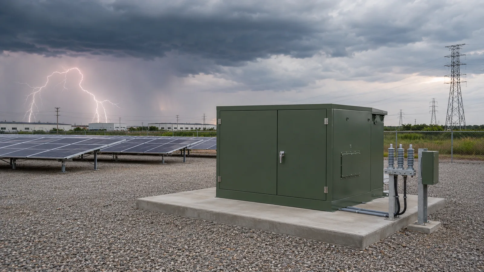
The electrical grid is not a perfectly stable environment. When lightning strikes a power line miles away, or when a large utility substation breaker opens or closes, a massive, microsecond-duration voltage spike travels down the line. When this surge reaches a pad mounted transformer, the internal insulation—the paper wrapping the coils, the mineral oil, and the physical clearances between energized parts and the grounded steel tank—must be robust enough to prevent the electricity from arcing across.
If the surge voltage exceeds the transformer's BIL rating, the insulation breaks down. This results in a catastrophic internal short circuit, boiling the insulating oil, generating massive internal pressure, and potentially rupturing the tank. Therefore, BIL is a critical safety parameter. It defines the absolute maximum transient voltage the transformer is guaranteed to survive without damage. Common BIL ratings for distribution transformers include 60kV, 75kV, 95kV, 125kV, and 150kV, depending on the primary voltage and the specific application environment.

4. How Primary Voltage and Insulation Class Affect BIL
There is a direct, standardized relationship between a transformer's primary voltage, its insulation class, and its required BIL. Higher primary voltages require higher BIL values, and BIL must be selected based on utility voltage class and protection requirements.
For example, a pad mounted transformer operating on a 4.16kV primary system (a 5kV voltage class) might require a 60kV BIL. However, a transformer operating on a 12.47kV or 13.8kV system (a 15kV voltage class) typically requires a 95kV BIL. If the primary voltage increases to 34.5kV (a 35kV voltage class), the required BIL jumps to 150kV.
However, buyers must be aware that utilities sometimes specify a higher BIL than the standard minimum for a given voltage class. For instance, in regions with exceptionally high lightning activity or at the end of long, exposed rural distribution lines, a utility might mandate a 125kV BIL for a 15kV class transformer to provide an extra margin of safety. This is why simply stating the primary voltage in an RFQ is insufficient; the specific BIL requirement, as dictated by the local utility or the project's design engineer, must be explicitly confirmed.

5. What is Impedance and Why It Affects Fault Current
Impedance, in the context of a pad mounted transformer, is the total opposition (resistance and reactance) that the transformer's internal windings present to the flow of alternating current. It is expressed as a percentage (%).
To understand why impedance is critical, one must look at what happens during a short circuit. If a fault occurs on the secondary side of the transformer (e.g., a dead short in the facility's main switchboard), the transformer will draw a massive amount of current from the primary grid to feed that fault. The only thing limiting that destructive fault current is the transformer's internal impedance.
A lower impedance value (e.g., 2.0%) means the transformer offers very little resistance to fault currents, allowing a massive surge of energy to pass through, which requires downstream breakers and fuses to have very high interrupting ratings. Conversely, a higher impedance value (e.g., 5.75%) restricts the maximum fault current, protecting downstream equipment but potentially causing a larger voltage drop during normal heavy load conditions (such as starting large industrial motors). Therefore, impedance is the balancing point between voltage regulation and short-circuit fault current limitation.
6. Why Buyers Should Not Guess Impedance Values
Because impedance directly dictates the maximum fault current, buyers should never guess or leave the impedance value blank on an RFQ, assuming the manufacturer will simply provide a "standard" value. Impedance selection depends on utility requirements, system design, protection coordination and fault current limits — buyers must confirm with utility and design engineer before RFQ.
If a buyer orders a transformer with an impedance of 4.0%, but the facility's main switchgear was engineered and purchased based on a transformer impedance of 5.75%, the switchgear's short-circuit rating may be inadequate. In the event of a fault, the switchgear could literally explode because it cannot safely interrupt the higher fault current allowed by the 4.0% impedance transformer.
Furthermore, if multiple transformers are operating in parallel, their impedances must match closely to ensure they share the load equally. A mismatch will cause one transformer to overload while the other is underutilized. Always consult the approved single-line diagram and the utility's interconnection requirements to confirm the exact impedance percentage required before requesting a quotation. For more context on feed layouts affecting your RFQ, see our guide on Loop Feed vs Radial Feed Pad Mounted Transformers.
7. BIL, Impedance, Bayonet Fuse and ELSP Fuse Coordination
The internal protection scheme of a pad mounted transformer is intimately tied to its BIL and impedance. The bayonet fuse and ELSP fuse are primary-side protection devices whose rating must be coordinated with transformer impedance, fault current capability and utility protection scheme.

The Bayonet Fuse is an oil-immersed, externally replaceable expulsion fuse designed to protect the transformer against secondary faults and severe overloads. Its sizing depends directly on the transformer's kVA rating and the expected normal load currents.
The ELSP Fuse (Current-Limiting Backup Fuse) is mounted internally in series with the bayonet fuse. Its job is to clear high-level internal faults—such as a primary winding failure—before the transformer tank can rupture. The ELSP fuse must be carefully selected based on the available fault current from the utility grid and the transformer's own impedance.
If the impedance is incorrect, the fault current calculations will be wrong, and the ELSP fuse may fail to clear a fault in time, or it may operate prematurely during normal transient events. Similarly, the physical clearances required for these fuses inside the high-voltage compartment are dictated by the BIL rating. A 150kV BIL transformer requires significantly more space between the fuses and the grounded tank than a 95kV BIL unit.

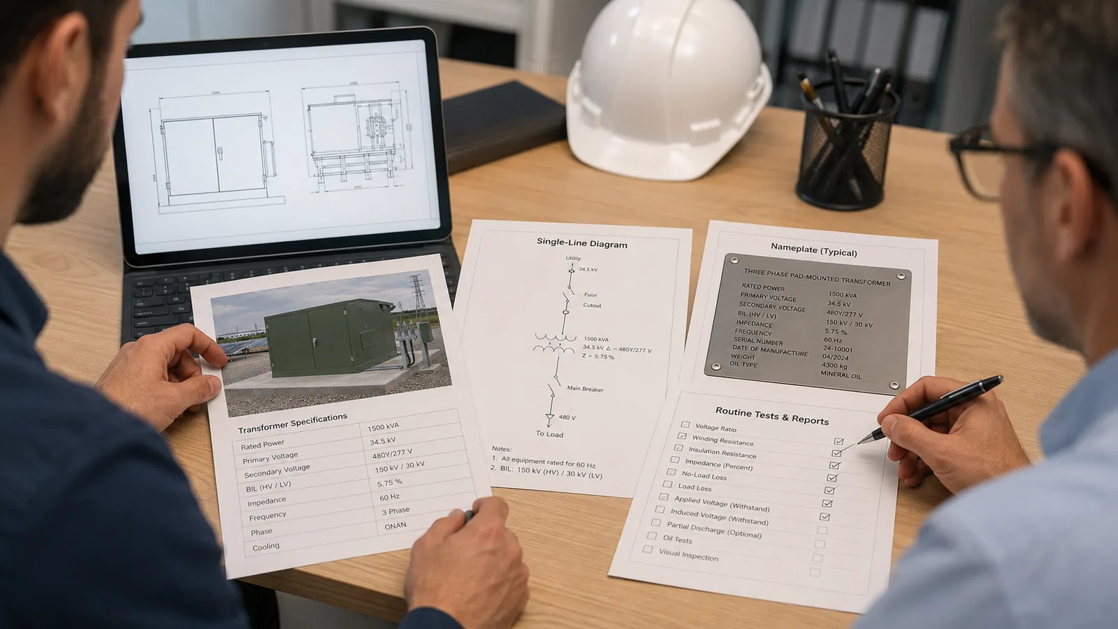
8. What a Pad Mounted Transformer Technical Sheet Should Show
To ensure a smooth procurement process and an accurate quotation, a comprehensive pad mounted transformer technical sheet must detail all critical electrical and physical parameters. When preparing an RFQ, buyers should ensure their specification includes:
- Rated Capacity (kVA): The total power output capability.
- Primary Voltage: The incoming utility voltage (e.g., 12470GrdY/7200V).
- Secondary Voltage: The outgoing facility voltage (e.g., 480Y/277V).
- Phase and Frequency: Three phase or single phase; 50Hz or 60Hz.
- Voltage Class and Insulation Class: Defines the overall system voltage category.
- BIL (Basic Impulse Level): The required transient withstand voltage (e.g., 95kV).
- Impedance (%): The required short-circuit impedance (e.g., 5.75%).
- Short-Circuit Capability and Fault Current: Maximum fault current limits.
- Single-Line Diagram: Shows the network arrangement and feed configuration (loop or radial).
- Protection Coordination: Details on upstream and downstream breaker ratings.
- Fusing Requirements: Specifics on bayonet fuse and ELSP fuse inclusion.
- Loadbreak Bushing: Quantity and rating for high-voltage connections.
- Grounding: Specific grounding pad and bar locations.
- Tap Changer: Off-circuit tap changer details (e.g., 5-position).
- Winding Material: Copper or Aluminum preference.
- Cooling Method: Typically ONAN (Oil Natural Air Natural).
- HV/LV Compartment Details: Dead-front design, specific dimensions, and cable entry direction.
- Standards and Testing Documents: Required IEEE, IEC, or utility-specific compliance and routine test reports.

9. Accessories, Dimensions and Protection Coordination Details
Beyond the core electrical data, the physical dimensions and accessories of a pad mounted transformer play a vital role in RFQ accuracy and utility approval. Accessories such as loadbreak bushings, tap changers, and cooling methods (like ONAN) significantly impact both the physical dimensions and operational safety of the equipment.
Accessories like oil level gauges, thermometers, pressure relief valves, and drain valves with samplers are often mandated by utility standards. The inclusion of a 5-position off-circuit tap changer allows operators to adjust the voltage ratio to compensate for grid fluctuations, but it requires specific internal clearances.
Furthermore, the physical dimensions of the transformer are heavily influenced by the BIL and impedance. A higher BIL requires a larger tank to maintain safe electrical clearances. A specific impedance requirement might necessitate a larger core, increasing the overall weight and footprint. If the RFQ does not specify these parameters, the quoted transformer might end up being too large for the pre-poured concrete pad or too heavy for the site's lifting equipment, causing severe installation delays.

10. Daniel's RFQ Review: Preventing Delays in an Industrial Park Expansion
The importance of confirming BIL and impedance is best illustrated by the experience of Daniel Reed, an EPC electrical engineer managing a large industrial park expansion. Daniel's team was tasked with procuring several 2500kVA pad mounted transformers to power new manufacturing facilities.
Initially, Daniel sent a very brief RFQ to several suppliers. The request listed only the capacity (2500kVA), the primary voltage (34.5kV), and the secondary voltage (480V). He assumed the manufacturers would fill in the blanks with standard industry values.
When the RFQ reached TransformerGrid, the engineering team immediately flagged the missing data. They contacted Daniel and reminded him to confirm the BIL, impedance, single-line diagram, fusing, utility requirements, testing documents, destination country, and delivery schedule before quotation.
Upon reviewing the utility's interconnection agreement and the site's single-line diagram, Daniel discovered critical details. Because the industrial park was at the end of a long 34.5kV distribution line in a high-lightning area, the utility strictly required a 150kV BIL, not the standard 125kV some suppliers might have assumed. Furthermore, the facility's main switchgear was rated for a specific fault current, mandating a strict transformer impedance of 5.75%. The utility also required specific bayonet and ELSP fusing coordination.
By conducting this early engineering review, TransformerGrid helped Daniel update his RFQ with the correct BIL, impedance, and protection requirements. This prevented Daniel from receiving inaccurate quotations, ordering non-compliant transformers, and facing catastrophic delays during utility inspection. The final delivered units matched the approved electrical design perfectly.
11. RFQ Checklist for BIL and Impedance Review
To ensure your pad mounted transformer RFQ is comprehensive and ready for accurate quotation, use the following checklist to verify all critical parameters:
| RFQ Item | Buyer Should Provide | Why It Matters |
|---|---|---|
| kVA Rating | Total capacity (e.g., 1500kVA) | Determines core size, weight, and power output. |
| Primary Voltage | Incoming utility voltage | Affects insulation class and HV bushing design. |
| Secondary Voltage | Outgoing facility voltage | Dictates LV terminal size and compartment depth. |
| Phase & Frequency | Three phase, 50Hz/60Hz | Fundamentally changes cabinet design and core loss calculations. |
| Voltage Class | e.g., 15kV, 35kV | Establishes the baseline for insulation requirements. |
| BIL Requirement | Basic Impulse Level (e.g., 95kV, 150kV) | Critical safety parameter for lightning and switching surge withstand. |
| Insulation Class | Temperature rise limits | Ensures long-term reliability under full load. |
| Impedance | Specific percentage (e.g., 5.75%) | Limits fault current and affects voltage regulation. |
| Short-Circuit Capability | Fault current limits | Ensures transformer survives external faults without mechanical damage. |
| Single-Line Diagram | Approved electrical schematic | Confirms feed configuration (loop/radial) and network architecture. |
| Protection Coordination | Upstream/downstream breaker data | Ensures fuses and breakers operate in the correct sequence. |
| Bayonet Fuse & ELSP Fuse | Specific ratings and inclusion | Primary-side protection against overloads and internal faults. |
| Loadbreak Bushing | Quantity and rating | Required for safe, dead-front high-voltage connections. |
| Grounding | Specific locations | Critical for safety and proper neutral bonding. |
| Tap Changer | e.g., 5-position off-circuit | Allows voltage adjustment for grid fluctuations. |
| Winding Material | Copper or Aluminum | Influences total footprint, weight, and cost. |
| Cooling Method | e.g., ONAN | Determines heat dissipation and fluid requirements. |
| HV & LV Compartment | Dimensions, cable entry | Ensures safe utility connections and proper cable bending radius. |
| Standards | e.g., IEEE, IEC, CSA | Provides the engineering framework for design and testing. |
| Testing Documents | Routine FAT reports, type tests | Missing documents may delay utility review, approval or energization. |
| Destination Country | Installation country | Identifies unique regional regulatory and safety standards. |
| Delivery Schedule | Target date on site | Allows supplier to plan production and shipping logistics. |
12. How TransformerGrid Helps Review BIL and Impedance Before Quotation
Procuring a pad mounted transformer is a complex engineering task that requires precision. TransformerGrid operates as a technical partner, not just a quotation generator. We offer early engineering review with no consulting fee and no pressure to order, positioning ourselves as a technical partner for early communication.
When a buyer submits a preliminary RFQ, single-line diagram, or utility specification, TransformerGrid engineers conduct a thorough review before issuing a quotation. They verify that the requested BIL aligns with the primary voltage class and local environmental risks. They cross-check the specified impedance against standard fault current limits and protection coordination requirements.
By identifying missing technical data—such as undefined fusing requirements or conflicting impedance values—early in the process, TransformerGrid helps buyers avoid costly quotation errors, manufacturing delays, and site rework. This ensures your project specifications are solid before procurement becomes urgent.
13. FAQ
Preparing a pad mounted transformer RFQ?
Send your kVA, primary voltage, secondary voltage, phase, frequency, BIL, impedance, single-line diagram, fusing requirement, accessories, project country, standards, testing document needs and delivery schedule.
TransformerGrid engineers can help review your pad mounted transformer BIL and impedance before quotation.
No consulting fee. No pressure to order. Just early technical communication before your project becomes urgent.